1. Uvod
Welcome to the user manual for the Autonics TC4S series temperature controllers, models TC4S-24R and TC4S-14R. These devices are designed for precise temperature regulation in various industrial and commercial applications. This manual provides essential information for safe and efficient operation, including installation, setup, operation, maintenance, and troubleshooting. Please read this manual thoroughly before operating the device and keep it for future reference.
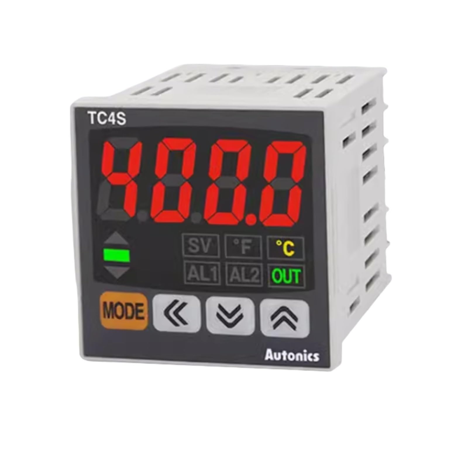
Slika 1: Spredaj view of the Autonics TC4S Temperature Controller. This image shows the display, control buttons, and indicator lights on the front panel of the device.
2. Varnostni ukrepi
To ensure safe operation and prevent product damage, observe the following safety precautions:
- Pred kakršnim koli ožičenjem ali vzdrževanjem vedno izklopite napajanje.
- Poskrbite za ustrezno ozemljitev, da preprečite električni udar.
- Enote ne razstavljajte ali spreminjajte. Vsa servisna dela prepustite usposobljenemu osebju.
- Install the unit in an environment free from excessive vibration, dust, moisture, and corrosive gases.
- Uporabite določen napajalnik voltage. Nepravilna zvtage lahko povzroči škodo.
- Ensure all wiring connections are secure and correct according to the wiring diagrams.
3. Izdelek je končanview
The Autonics TC4S series temperature controllers feature a compact design and precise control capabilities. Key components include:
- Zaslon: Shows current temperature (PV) and set temperature (SV).
- Gumbi za upravljanje: Used for setting parameters and navigating menus.
- Indikatorske lučke: Provide status feedback (e.g., output ON, alarm).
- Terminalni blok: Located at the rear for power, sensor input, and control output connections.
4. Namestitev in ožičenje
4.1 Montaža
The TC4S series controllers are designed for panel mounting. Ensure adequate space for ventilation and wiring connections. Cut a panel opening of the specified dimensions (refer to specifications for exact cutout size). Insert the controller into the opening and secure it using the provided mounting brackets.
4.2 Ožičenje
Connect the power supply, temperature sensor, and control output devices to the terminal block at the rear of the controller. Refer to the wiring diagram typically found on the side of the unit or in the full product datasheet for specific terminal assignments. Ensure all connections are tight and correct to prevent malfunction or damage.
- Napajanje: Connect to the designated power terminals (e.g., 100-240VAC).
- Vhod senzorja: Connect your temperature sensor (e.g., thermocouple, RTD) to the sensor input terminals. Observe polarity for thermocouples.
- Izhod krmiljenja: Connect your heating/cooling element or relay to the control output terminals. Model TC4S-24R typically features a relay output, while TC4S-14R may have a different output type.
5. Začetna nastavitev
5.1 Vklop
After completing all wiring, apply power to the controller. The display will typically show the current process value (PV) and the set value (SV). The unit will perform a self-test upon initial power-up.
5.2 Basic Parameter Settings
Access the parameter settings menu using the designated buttons (e.g., MODE or SET button). Common initial settings include:
- Vrsta vnosa: Select the type of temperature sensor connected (e.g., K-type thermocouple, Pt100 RTD).
- Enota za temperaturo: Choose between Celsius (°C) or Fahrenheit (°F).
- Nadzorni način: Select between ON/OFF control or PID control, depending on application requirements.
Refer to the detailed parameter list in the full product manual for advanced settings and their functions.
6. Delovanje
6.1 Setting the Target Temperature (Set Point)
To set the desired temperature, press the SET button. The SV display will flash, allowing you to adjust the value using the UP/DOWN arrow buttons. Press SET again to confirm the new set point.
6.2 Razumevanje indikatorjev na zaslonu
- PV (vrednost procesa): Displays the current measured temperature.
- SV (Nastavljena vrednost): Prikaže ciljno temperaturo.
- Indikator OUT: Illuminates when the control output is active (e.g., heating element is ON).
- Indikator ALM: Illuminates when an alarm condition is met.
6.3 Načini krmiljenja
The controller supports different control modes:
- Nadzor VKLOP/IZKLOP: The output turns ON when the PV is below the SV and OFF when it exceeds the SV (or vice versa for cooling). This mode is simple but can lead to temperature cycling.
- PID regulacija: Proportional-Integral-Derivative control provides more precise and stable temperature regulation by calculating the required output based on the error, integral of the error, and derivative of the error. Auto-tuning functions are often available to automatically calculate optimal PID parameters.
7. Vzdrževanje
7.1 Čiščenje
Regularly clean the front panel with a soft, dry cloth. Do not use abrasive cleaners, solvents, or water, as these can damage the display or internal components.
7.2 Pregled
Periodically inspect wiring connections for looseness or signs of damage. Ensure the ventilation openings are not obstructed. Check for any unusual noises or smells during operation.
7.3 Shranjevanje
If storing the unit for an extended period, ensure it is kept in a dry, dust-free environment within the specified storage temperature and humidity ranges.
8. Odpravljanje težav
This section addresses common issues you might encounter with your temperature controller.
| Težava | Možen vzrok | rešitev |
|---|---|---|
| Krmilnik se ne vklopi | Ni napajanja; napačna napeljava; pregorela varovalka. | Check power connections; verify wiring against diagram; replace fuse if necessary. |
| Incorrect temperature reading (PV) | Sensor disconnected or faulty; incorrect sensor input type setting; sensor outside measurement range. | Check sensor wiring and connection; verify sensor type setting in parameters; ensure sensor is suitable for the temperature range. |
| Output not activating | Set point not reached; output mode incorrect; faulty output device; alarm condition active. | Adjust set point; check control mode (ON/OFF, PID); test external heating/cooling device; check alarm settings. |
| Temperatura močno niha | PID parameters not tuned correctly; ON/OFF control with large hysteresis. | Perform auto-tuning for PID parameters; adjust hysteresis for ON/OFF control. |
9. Specifikacije
Key technical specifications for the Autonics TC4S series temperature controllers:
- Modeli: TC4S-24R, TC4S-14R
- Nadzorna metoda: ON/OFF krmiljenje, P, PI, PD, PID krmiljenje
- Vhodni senzor: Thermocouple (K, J, T, E, N, R, S, B, C, G, L, U, P), RTD (Pt100, JPt100) - Specific types may vary by model.
- Vrsta izhoda: Relay output (TC4S-24R), SSR drive output, Current output - Specific type varies by model.
- Napajanje: 100-240VAC 50/60Hz (standard), 24VAC 50/60Hz / 24-48VDC - Specifični voltage se razlikuje glede na model.
- Način prikaza: 7-segment LED (PV: red, SV: green)
- Natančnost nadzora: ±0.5% FS ±1 digit (thermocouple/RTD)
- Material: Plastika casing
- Delovna temperatura: -10 °C do 50 °C (14 °F do 122 °F)
- Delovna vlažnost: 35 do 85 % RH (brez kondenzacije)
10. Garancija in podpora
This Autonics temperature controller is covered by a standard manufacturer's warranty against defects in materials and workmanship. The warranty period typically begins from the date of purchase. Please retain your proof of purchase for warranty claims.
For technical support, service, or warranty inquiries, please contact your authorized Autonics distributor or the customer support department. Provide the model number (TC4S-24R or TC4S-14R) and a detailed description of the issue when seeking assistance.
For the most up-to-date contact information and detailed warranty terms, please visit the official Autonics webspletno mesto ali si oglejte dokumentacijo, ki ste jo prejeli ob nakupu.